2009 Challenger RT/SRT
PowerDistribution
The power distribution system also incorporates various types of circuit control and protection features, including:
Automatic resetting circuit breakers
Blade-type fuses
Cartridge fuses
Relays
Mini fuses
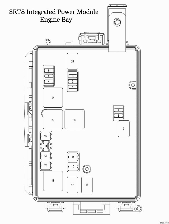
Total Integrated Power Module (FRONT Engine Bay)
Cavity |
Cartridge Fuse |
Mini-Fuse |
Description |
|
1 |
— |
15 Amp Blue |
Washer Motor |
|
2 |
— |
25 Amp Neutral |
Powertrain Control Module (PCM) |
|
3 |
— |
25 Amp Neutral |
Ignition Run/Start |
|
4 |
— |
25 Amp Neutral |
Alternator |
|
5 |
— |
— |
— |
|
6 |
— |
25 Amp Neutral |
Ignition Coils/Injectors |
|
7 |
— |
— |
— |
|
8 |
— |
25 Amp Neutral |
Starter |
|
9 |
— |
— |
— |
|
10 |
30 Amp Pink |
— |
Windshield Wiper |
|
11 |
30 Amp Pink |
— |
Anti-lock Brake System (ABS) Valves |
|
12 |
40 Amp Green |
— |
Radiator Fan |
|
13 |
50 Amp Red |
— |
Anti-lock Brake System (ABS) Pump Motor |
|
14 |
— |
— |
— |
|
15 |
50 Amp Red |
— |
Radiator Fan |
|
16 |
— |
— |
— |
|
17 |
— |
— |
— |
|
18 |
— |
— |
— |
|
19 |
— |
— |
— |
|
20 |
— |
— |
— |
|
21 |
— |
— |
— |
|
22 |
— |
— |
— |
Rear Power Distribution
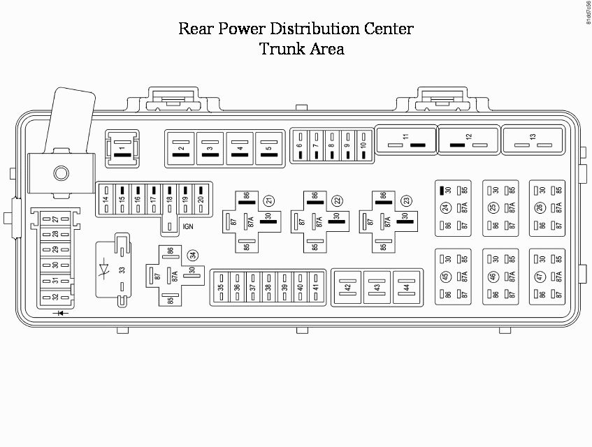
Cavity |
Cartridge Fuse |
Mini-Fuse |
Description |
|
1 |
60 Amp Yellow |
— |
Ignition Off Draw (IOD) |
|
2 |
40 Amp Green |
— |
Integrated Power Module (IPM) |
|
3 |
— |
— |
— |
|
4 |
40 Amp Green |
— |
Integrated Power Module (IPM) |
|
5 |
30 Amp Pink |
— |
Heated Seats - if equipped |
|
6 |
— |
20 Amp Yellow |
Fuel Pump |
|
7 |
— |
20 Amp Yellow |
Sub Amp - if equipped |
|
8 |
— |
15 Amp Blue |
Diagnostic Link Connector (DLC)/Wireless Ignition Node (WIN) |
|
9 |
— |
20 Amp Yellow |
Power Outlet |
|
10 |
— |
— |
— |
|
11* |
— |
— |
— |
|
12* |
— |
— |
— |
|
13* |
— |
— |
— |
|
14 |
— |
10 Amp Red |
AC Heater Control/Cluster/Security Module - if equipped |
|
15 |
— |
20 Amp Yellow |
— |
|
16 |
— |
20 Amp Yellow |
— |
|
17 |
— |
20 Amp Yellow |
Cluster |
|
18 |
— |
20 Amp Yellow |
Selectable Power Outlet |
|
19 |
— |
10 Amp Red |
Stop Lights |
|
20 |
— |
— |
— |
|
21 |
— |
— |
— |
|
22 |
— |
— |
— |
|
23 |
— |
— |
— |
|
24 |
— |
— |
— |
|
25 |
— |
— |
— |
|
26 |
— |
— |
— |
|
27 |
— |
10 Amp Red |
Occupant Restraint Controller (ORC) |
|
28 |
— |
10 Amp Red |
Ignition Run |
|
29 |
— |
5 Amp Orange |
Cluster/Electronic Stability Program (ESP)/Powertrain Control Module (PCM)/STOP LIGHT Switch |
|
30 |
— |
10 Amp Red |
Door Modules/Power Mirrors/Steering Control Module (SCM) |
|
31 |
— |
— |
— |
|
32 |
— |
— |
— |
|
33 |
— |
— |
— |
|
34 |
— |
— |
— |
|
35 |
— |
5 Amp Orange |
Antenna Module - if equipped/Power Mirrors/Rain Sensor - if equipped |
|
36 |
— |
20 Amp Yellow |
Hands-Free Phone - if equipped/Video Monitor - if equipped/Radio |
|
37 |
— |
15 Amp Blue |
Transmission |
|
38 |
— |
10 Amp Red |
Cargo Light/Vehicle Information Module - if equipped |
|
39 |
— |
10 Amp Red |
Heated Mirrors - if equipped |
|
40 |
— |
5 Amp Orange |
Auto Inside Rearview Mirror/Heated Seats - if equipped/Switch Bank |
|
41 |
— |
10 Amp Red |
AC Heater Control/Headlights/Park Assist - if equipped/Tire Pressure Monitoring - if equipped/Occupant Restraint Controller (ORC) |
|
42 |
30 Amp Pink |
— |
Front Blower Motor |
|
43 |
30 Amp Pink |
— |
Rear Window Defroster |
|
44 |
20 Amp Blue |
— |
Amplifier - if equipped/Sunroof - if equipped |
*Cavities 11, 12, and 13 contain self-resetting fuses (circuit breakers) that are only serviceable by an authorized dealer.
The Passenger Seat Switch is fused by the 25 amp circuit breaker in Cavity 12. The Door Modules (except base), the
Driver Door Lock Switch (base), the Driver Express Power Window Switch (if equipped), and the Passenger Door
Lock Switch (base) are fused by the 25 amp circuit breaker in Cavity 13.
If you experience temporary or permanent loss of these systems, see your authorized dealer for service.