Challenger 2008-2010
EVAPORATIVE SYSTEM
INTEGRITY MONITOR
OPERATION
The ESIM (Evaporative System
Integrity Monitor) is very similar to the earlier NVLD (Natural Vacuum Leak
Detection) system.
However,
the design of the ESIM has been simplified and unlike the NVLD the ESIM does
not require a solenoid.
The ESIM mounts directly to the canister, eliminating the need for a mounting
bracket. It is critical that the ESIM
is mounted vertically. On vehicles where the canister is mounted on an angle,
the ESIM requires an adaptor to
maintain a vertical position.
When
the ESIM is installed vertically, the electrical connector is in the 3 o'clock
position.
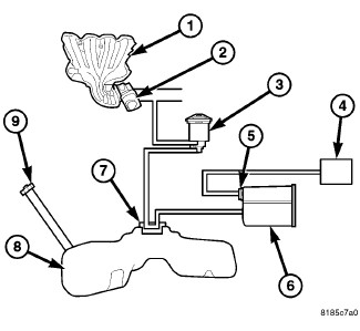
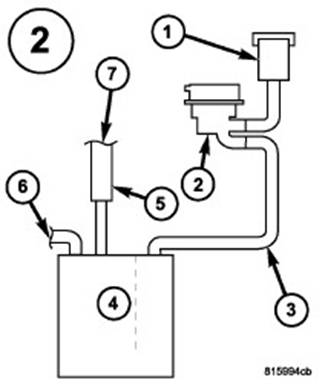
SYSTEM
1 - Intake Manifold
2 - Throttle Body
3 - Purge Solenoid
4 - Filter
5 - ESIM
6 - Vapor Canister
7 - Control Valve
8 - Fuel Tank
9 - Gas Cap
The
ESIM assembly consists of a housing, a small weight and a large weight that
serve as check valves, a diaphragm, a switch and a cover. There is one large
weight and one small weight check valve in the ESIM assembly. A seal is
attached at the end of each weighted check valve. The large weight check valve
seals for pressure.
The small weight check valve seals for
vacuum. The weighted check valves are contained within the ESIM housing
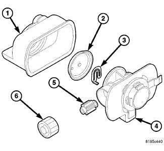
EXPLODED VIEW
1
- ESIM Housing
2
- Diaphragm
3
- Switch
4
- Cover
5
- Small Check Valve
6
- Large Check Valve
The
ESIM (Evaporative System Integrity Monitor), while physically different than
the NVLD system, performs the same
basic function as the NVLD does – controlling evaporative emissions. The ESIM
has been simplified because the
solenoid used on the NVLD is not used on
the ESIM.
The
ESIM consists of housing, two check valves (sometimes referred to as weights),
a diaphragm, a switch and a cover.
The larger check valve seals for pressure and
the smaller one seals for vacuum.
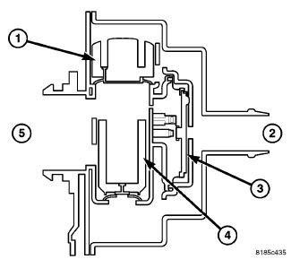
CUT AWAY OF MODULE
1 - Large
Check Valve
2 - Fresh
Air Inlet
3 -
Diaphragm
4 - Small
Check Valve
5 - Vapor Canister
Refueling
During
refueling, pressure is built up in the evaporative system. When pressure approximately .5 inches of
water, the large
check valve unseats and pressure vents to the fresh air filter.
Conversely,
when the system cools and the resulting vacuum lifts the small check valve from
its seat and allows fresh air to
enter the system and relieve the vacuum condition. When a calibrated amount of
vacuum is achieved in the evaporative
system, the diaphragm is pulled inward, pushing on the spring and closing the
contacts.
The
ESIM conducts test on the evaporative system as follows: An engine off,
non-intrusive test for small leaks and an engine
running, intrusive test for medium/large leaks.
The
ESIM weights seal the evap. system during engine off conditions. If the evap.
system is sealed, it will be pulled into a
vacuum, either due to the cool down from operating temperature or diurnal
ambient temperature cycling. When the vacuum
in the system exceeds about 1” H20, the vacuum switch closes. The switch
closure sends a signal to the NGC. In order to
pass the non-intrusive small leak test, the ESIM switch must close within a
calculated amount of time and within a specified
amount of key-off events.
If the ESIM switch does not close as
specified, the test is considered inconclusive and the intrusive engine running
test will
be run during the next key-on cycle. This intrusive test will run on the next
cold engine running condition.
Conditions
for running the intrusive test are:
After the vehicle is started, the engine coolant temperature must
be within 10° C (50°F)
of ambient to indicate a cold start.
The fuel level must be between 12% and 88%.
The engine must be in closed loop.
Manifold vacuum must be greater than a minimum specified value.
Ambient temperature must be between 4° C and 37° C (39° F and 98°
F) and the elevation level must be below 8500 feet.
The
test is accomplished by the NGC activating the purge solenoid to create a
vacuum in the evaporative system.
The
NGC then measures the amount of time it takes for the vacuum to dissipate. This
is known as the vacuum decay method.
If the switch opens quickly a large leak is recorded. If the switch opens after
a predetermined amount of time, then the small
leak matures. If the switch does not close, then a general evaporative failure
is recorded.
The
purge monitor tests the integrity of the hose attached between the purge valve
and throttle body/intake. The purge monitor
is a two stage test and it runs only after the evaporative system passes the
small leak test.
Even
when all of the thresholds are met, a small leak won’t be recorded until after
the medium/large leak monitor has been
run. This is accomplished by the NGC activating the purge solenoid to create a
vacuum in the evaporative system. The NGC
then measures the amount of time it takes for the vacuum to dissipate. This is
known as the vacuum decay method. If the
switch opens quickly a large leak is recorded. If the switch opens after a
predetermined amount of time, then the small leak
matures.
If the medium/large leak test runs and the ESIM switch doesn’t close, a general
evaporative test is run.
The
purge solenoid is activated for approximately 10 seconds, increasing the amount
of vacuum in the system. IF the ESIM
switch closes after the extended purge activation, a large leak fault is
generated. If the switch doesn’t close, a general
evaporative system fault is generated.
The
purge monitor tests the integrity of the hose attached between the purge valve
and throttle body/intake. The purge
monitor is a two stage test and it runs only after the evaporative system
passes the small leak test.
Stage
one of the purge monitor is non-intrusive. NGC monitors the purge vapor ratio.
If the ratio is above a calibrated
specification, the monitor passes. Stage two is an intrusive test and it runs
only if stage one fails. During the stage two
test, the GPEC commands the purge solenoid to flow at a specified rate to force
the purge vapor ratio to update. The
vapor ratio is compared to a calibrated specification and if it is less than
specified, a one-trip failure is recorded.
The
ESIM switch stuck closed monitor checks to see if the switch is stuck closed.
This is a power down test that runs at
key-off; when the NGC sees 0 rpm’s, the purge solenoid is energized for a
maximum of 30 seconds, venting any vacuum
trapped in the evaporative system. If the switch opens or was open before the
test began, the monitor passes. If the switch
doesn’t open, the monitor fails. This is a two-trip MIL.
The
star scan tool can be used to force the ESIM switch stick closed monitor to
run.
The
NGC also uses the ESIM to detect a loose or missing gas cap. The NGC controller
looks for a change in the fuel level
(25% minimum) and then gas cap is loose or missing. If a medium/large leak is
detected, a loose gas cap light illuminates
and a pending one-trip fault code is set. On the NGC, this is a three-trip
fault before the code matures
The larger check valve seals for pressure and
the smaller one seals for vacuum.
CHECKING THE
EVAPORATIVE SYSTEM
FOR LEAKS
Service Procedure
For a complete wiring diagram Refer to the Wiring Information.
1. EVAPORATIVE SYSTEM INSPECTION
|
Turn the ignition off. |
|
2. |
Raise the vehicle as necessary in
accordance with the Service Information. |
|
3. |
Perform a thorough inspection on the
evaporative/fuel system. Check for the following conditions:
|
Were any problems found?
Yes
Repair as necessary.
Perform the PCM Verification Test.
(Refer to 28 - DTC-Based Diagnostics/MODULE,
Powertrain Control (PCM) - Standard Procedure)
No
Go to 2
2. EVAPORATIVE SYSTEM LEAK
|
To test the evaporative system for leaks
you will need Miller Tool #8404A Evaporative Emission Leak Detector (EELD). |
|
WARNING: |
Keep lit cigarettes, sparks,
flames, and other ignition sources away from the test area to prevent the
ignition |
|
NOTE: |
The fuel tank should have
between 20% and 80% of fuel tank capacity to properly test the EVAP system. |
|
2. |
Connect the red power lead of the EELD to
the battery positive terminal and the black ground lead to battery negative
terminal. |
|
3. |
Connect shop air to the EELD. |
|
4. |
Set the smoke/air control switch to AIR. |
|
5. |
Insert the tester's AIR supply tip (clear
hose) into the appropriate calibration orifice on the tester's control panel
(based on DTC leak size). |
|
6. |
Press the remote smoke/air start button. |
|
7. |
Position the red flag on the air flow meter
so it is aligned with the indicator ball. |
|
8. |
When the calibration is complete, release
the remote button. The EELD flow meter is now calibrated in liters per minute
to the size leak indicated by the DTC set in the PCM. |
|
9. |
Install the service port adapter #8404-14
on the vehicle's service port and block the vent hose of the EVAP canister
(if equipped) or install the #8404-ADP service adapter into the filter line. |
|
10. |
Connect the AIR supply hose from the EELD
to the service port (if equipped) or to the #8404-ADP adapter. |
|
11. |
Press the remote button to activate AIR
flow. |
|
NOTE: |
Vehicles with large volume fuel
tanks, lower fuel levels, or vehicles equipped with a flow |
|
12. |
Compare the flow meter indicator ball
reading to the red flag. |
|
13. |
ABOVE the red flag indicates that a leak
present. |
|
14. |
BELOW the red flag indicates that the
system is sealed. |
Is the indicator ball above the red flag?
Yes
Go to 3
No
Refer to the Freeze Frame data, if applicable. If the Freeze Frame
data indicates that the vehicle was in
motion when the DTC was set, verify that all hoses are connected properly.
Perform the PCM Verification Test.(Refer to 28 - DTC-Based Diagnostics/MODULE,
Powertrain Control (PCM) - Standard Procedure)
3. EVAPORATIVE EMISSION LEAK DETECTION
|
NOTE: |
A thorough inspection of the EVAP system hoses, tubes, and
connections may save time in diagnosis. |
|
1. |
To continue testing, you will need Miller
Tool #8404A Evaporative Emissions Leak Detector (EELD). |
|
2. |
Remove the AIR supply hose from the service
port (if equipped) or from the #8404-ADP adapter. |
|
3. |
Connect the SMOKE supply tip (black hose)
to the service port (if equipped) or to the #8404-ADP adapter. |
|
4. |
Set the smoke/air control switch to SMOKE. |
|
NOTE: |
The flow meter indicator ball
will not move in the smoke mode. |
|
5. |
Press the remote smoke/air start button. |
|
NOTE: |
Make sure that smoke has filled
the EVAP system by continuing to press the remote |
|
NOTE: |
For the best results, introduce
smoke into the system for an additional 60 seconds |
|
6. |
While still holding the remote smoke/air
start button, use the white light (#8404-CLL) to follow the EVAP system path,
and look for the source of the leak as indicated by exiting smoke. |
|
7. |
If a leak is concealed from view (at the
top of the fuel tank, for example), release the remote smoke/air start
button, and use the ultraviolet (UV) black light #8404-UVL and the yellow
goggles 8404-20 to look for residual traces of dye that is left behind by the
smoke. |
|
8. |
The exiting smoke deposits a residual fluid
that is either bright green or bright yellow when viewed with a UV light. |
Were any problems found?
Yes
Repair or replace the leaking component as necessary.
Perform the PCM Verification Test.
(Refer to 28 - DTC-Based Diagnostics/MODULE,
Powertrain Control (PCM) - Standard Procedure)
No
Go to 4
4. CHECKING THE GAS CAP AND FUEL FILLER TUBE
|
Thoroughly check the gas cap and filler
tube area for leaks. |
Was a leak found at the gas cap or filler tube?
Yes
Go to 5
No
Go to 6
5. GAS CAP OR FUEL FILLER TUBE
|
Remove the SMOKE supply tip (black hose)
from the service port (if equipped) or from the #8404–ADP adapter. |
|
2. |
Install gas cap adapter, Miller Tool #8382
(1/4 turn cap) or #6922 (screw cap) and #8399* (secondary seal depressor) and
repeat test 4. |
Was a leak found at the gas cap adapter?
Yes
Replace the fuel filler tube assembly.
Perform the PCM Verification Test.
(Refer to 28 - DTC-Based Diagnostics/MODULE,
Powertrain Control (PCM) - Standard Procedure)
No
Replace the gas cap.
Perform the PCM Verification Test.
(Refer to 28 - DTC-Based Diagnostics/MODULE,
Powertrain Control (PCM) - Standard Procedure)
6. CHECKING FOR EVAPORATIVE SYSTEM LEAKS IN ZONE 1
|
|
|
NOTE: |
For testing purposes, the EVAP
System is divided into three zones. |
|
1. |
Using the list below, check each of the
components in Zone 1 of the evaporative system for leaks:
|
Were any problems found?
Yes
Repair or replace the leaking component as necessary.
Perform the PCM Verification Test.
(Refer to 28 - DTC-Based Diagnostics/MODULE,
Powertrain Control (PCM) - Standard Procedure)
No
Go to 7
7. CHECKING FOR EVAPORATIVE SYSTEM LEAKS IN ZONE 2
|
|
|
NOTE: |
For testing purposes, the EVAP
System is divided into three zones. A leak from any of these zones can cause
a DTC to set. The lists in the following steps below specify possible leak
points in one of the specific zones. |
|
1. |
Using the list below, check each of the
components in Zone 2 of the evaporative system for leaks:
|
Were any problems found?
Yes
Repair or replace the leaking component as necessary.
Perform the PCM Verification Test.
(Refer to 28 - DTC-Based Diagnostics/MODULE,
Powertrain Control (PCM) - Standard Procedure)
No
Go to 8
8. CHECKING FOR EVAPORATIVE SYSTEM LEAKS IN ZONE 3
|
|
|
NOTE: |
For testing purposes, the EVAP
System is divided into three zones. |
|
1. |
Using the list below, check each of the
components in Zone 3 of the evaporative system for leaks:
|
Were any problems found?
Yes
Repair or replace the leaking component as necessary.
Perform the PCM Verification Test.
(Refer to 28 - DTC-Based Diagnostics/MODULE,
Powertrain Control (PCM) - Standard Procedure)
No
Test is complete.